
Co-Axis Surgical Protocol
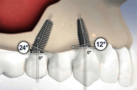
Initially designed with a 12º sub-crestal angulation to match the natural tooth and root relationship and to overcome the anatomical constraints of the anterior maxilla, the Co-Axis implant is providing clinicians with the ability to offer their patients simple screw retained prosthesis without the need for bone grafting, bulky angled abutments or costly custom abutments, in all the popular connection systems offered by Southern Implants.
Also available in 24º or 36º angles incorporated into the implant sub-crestally, these External Hex Co-Axis implant can be placed into the available bone to facilitate the emergence of the restorative platform at the optimal prosthetic angle in a variety of positions in the mouth. For example, mesiodistal angulation allows for avoidance of the sinus or inferior alveolar nerve, while reducing the cantilever of full-arch prosthetics. Once incorporated into treatment planning, the Co-Axis implant becomes an incredibly valuable solution for everyday complications.
Surgical Protocol
(External Hex 12º Co-Axis ø5 x 13mm)
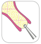 |
Step 1 A full-thickness mucoperiosteal flap is elevated and the alveolar bone is exposed. The Round Burr (D-RB) is used to initiate the osteotomy by perforating the cortical plate at the desired location. |
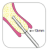 |
Step 2 The ø2mm Twist Drill (D-20T-M15) has markings at the lengths of 7, 10, 13 and 15mm and should be inserted to the required depth at 1000-2000rpm, with copious irrigation. Insertion should be just palatal to the incisal edge of the adjacent teeth. Note: Over-preparation in length of 1-2mm is recommended where safe to do so with this drill. |
 |
Step 3 Insert the Direction Indicator (I-DI-12d) after using each Twist Drill to verify the alignment and cingulum access with adjacent teeth/implants and the opposing occlusion. |
 |
Step 4 The ø3mm Twist Drill (D-30T-M15) has markings at the lengths of 7, 10, 13 and 15mm and should be inserted to the required depth at 1000-2000rpm, with copious irrigation. |
|
Step 5 Insert the Direction Indicator (I-DI-12d) after using each Twist Drill to verify the alignment and cingulum access with adjacent teeth/implants and the opposing occlusion. |
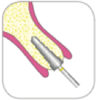 |
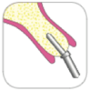
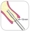
Step 6 The final ø5mm by 13mm Tapered Drill (D-50TP-13), which is slightly smaller than the implant selected, is then inserted to the required depth at approximately 500 to 800rpm. Bone Taps are available (D-TAP-IBT) for use in dense bone conditions in the mandible. |
|
Step 7 Check final depth before placing implant using the Depth Gauge (I-DG) with markings at 7, 10, 11.5, 13 and 15mm. |
|
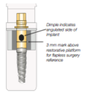 |
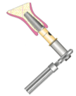
Step 8 The 12º Co-Axis Implant is supplied with a fixture mount. The fixture mount features a 12º-angle correction. This results in a straight implant/fixture mount assembly. Dimple indicates the angulated side of the implant. Note: Make sure the fixture mount screw is tight during placement of implant. Loosening of screw can result in stripping of the implant hex. |
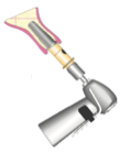 |
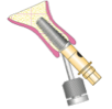
Step 9 The Handpiece Connector (I-CON-X) is inserted into the handpiece and placed over the fixture mount. The implant is removed from sterile vial and inserted into the osteotomy site at 15-20rpm and approximately 45Ncm. Note: Implant should be inserted no less than 2mm from the Buccal Plate. |
 |
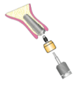
Step 10 Remove the I-CON-X from the fixture mount and insert the Fixture Mount Extender (I-FME-X) into the Ratchet Wrench (I-RATCHET-2) engaging the fixture mount to fully seat the implant making sure the angle of the implant is in the correct position. Reminder: The dimple is indicates the highest point of the implant, i.e. is located opposite to the shallowest part of the occlusal platform. |
 |
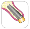
Step 11 Once the implant is fully seated, the fixture mount is disengaged from the implant with the Hex Driver (I-HD). Note: I-HD position is illustrating screw access. Note: To allow correct healing abutment and prosthetic seating, lingual bone may need to be removed, either at this point with a bone mill, or prior to placing the implant with a burr. |
 |
Step 12 In a one-stage protocol, the Healing Abutment can now be placed using the Hex Driver (I-HD) and the flap margins are position around the Healing Abutment and sutured in a tension-free manner. |
 |